Manual Stepped Voltage Stabilizer Circuit Diagram

Description Here Is The Circuit Diagram Of A Powerful 12v Regulator That Can Deliver Up To 15 A Of Cur Voltage Regulator Circuit Diagram Electronic Schematics

100 Power Supply Circuit Diagram With Pcb Eleccircuit Com Power Supply Circuit Simple Electronic Circuits Electronic Circuit Projects

Automatic Voltage Stabilizer Circuit Diagram Circuit Diagram Circuit Pic Microcontroller

Usb 5v To 1 5v 3v Step Down Converter Circuit Eleccircuit Com Circuit Usb Battery Charger Circuit
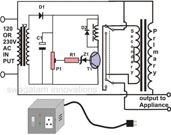
How To Make An Automatic Voltage Stabilizer Circuit Construction Explained Bright Hub Engineering

Automatic Voltage Stabilizer Circuit Diagram Circuit Diagram Circuit Diagram

Then the transformer output is rectified by bridge rectifier.
Manual stepped voltage stabilizer circuit diagram.

Lm350 Voltage Regulator Circuit Diagram Voltage Regulator Electronics Projects Regulators

Solid State Scr Triac Controlled Automatic Voltage Stabilizer Circuit Projects Circuit Electronics Circuit

Voltage Stabilizer Wiring Diagram Automotive Electrical Diagram Bp Oil

How To Use Hall Effect Sensor With Arduino Working Hook Up Guide And Relay Control In 2020 Hall Effect Arduino Sensor
Source : pinterest.com
